Path Finding Part 1
If you have not already done so I suggest you look at the path finding library guide.
This is the first part of a two-part guide describing how to implement the path-finding steering behaviour. This part describes how to create a navigation graph to define the paths through the game world.
Navigation Graph
The source code in this guide comes from the library example sketch "PathFinding_01". When this sketch is executed it creates and displays the following simple navigation graph.
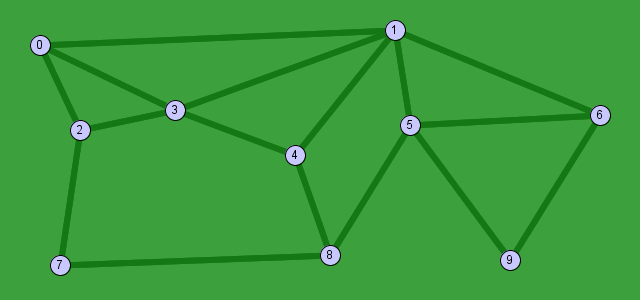
You can see that the graph has 10 'nodes' and 16 paths (dark green lines). In this graph each path can be traversed in both directions, so it means there are 32 'edges' in the graph.
The first thing to do is to create an empty graph, this can be done with -
Graph graph = new Graph();Creating and added the nodes
Although it is possible to create the nodes and edges in any order, it is much more efficient to create and add the nodes before the edges. The following code will create and add the first three nodes for this graph.
GraphNode node;
//                  ID    X    Y
node = new GraphNode(0,  40,  45);
graph.addNode(node);
node = new GraphNode(1, 395,  30);
graph.addNode(node);
node = new GraphNode(2,  80, 130);
graph.addNode(node);
The GraphNode is the main class used to represent a node and needs three pieces of information when creating a node -
- ID - this can be any positive integer (including zero). It is essential that different nodes have different ID numbers. Attempt to have 2 or more nodes with the same ID number will corrupt the navigation map layout.
- X - the horizontal location of the node in world coordinates
- Y - the vertical location of the node in world coordinates
The ID numbers used do not have to start at zero, or be continuous, so you can create your own numbering scheme when deciding on the actual numbers to be used.
Creating and added the edges
Now that you have added the nodes it is time to add the edges. Remember an edge is describes a one-way connection between two nodes, if the connection is to be two-way then this requires two edges. The following code adds the edges for nodes 0 and 1.
// Edges for node 0
graph.addEdge(0, 1, 0, 0);
graph.addEdge(0, 2, 0, 0);
graph.addEdge(0, 3, 0, 0);
// Edges for node 1
graph.addEdge(1, 3, 0, 0);
graph.addEdge(1, 4, 0, 0);
graph.addEdge(1, 5, 0, 0);
graph.addEdge(1, 6, 0, 0);
The
addEdge()
method requires 3 or 4 pieces of information depending on whether
the connection is one or two-way.
- ID number of the 'start' node for this connection
- ID number of the 'end' node for this connection
- The 'cost' of travelling from the start node to the end node (required).
- The 'cost' of travelling from the end node to the start node (optional).
Item (4) is only required if the connection is two-way and if different to (3) then it will be easier to travel in one direction compared with the other direction.
If the cost is 0 (zero) then the graph will calculate the cost as the distance between the two nodes.